Ensemble RXTX - Ensemble RX III: Power Supply
Band: HF
Introduction
HamNation Video of this Stage's Build
You might be interested in watching George Thomas' (W5JDX) HamNation presentation of building this (and the following) stage (the presentation begins at 36:30 into the video). Of particular interest is the use of solder paste (obtainable from Cash Olsen) and an embossing gun ( the ~$20 "Hobby Lobby" StampAire) to install the SMT parts.
General Info About the Stage
In this first (and following) stages, the builder should remember that one of the most common causes of errors is soldering. It pays to review materials on soldering, get help from Elmers, or whatever you can do to make your solder joints as clean and properly conductive as possible!
The second most common cause of errors is installation of the WRONG component and/or installing the component in the wrong ORIENTATION. The old rule of "measure twice, cut once" clearly applies to this project. Be especially careful and beware that it is very easy to install the wrong resistor depending entirely in color codes. While color codes are helpful in initially sorting resistors out, it is imperative that you validate that you have the correct resistor by double checking with your ohmmeter. While the ohmmeter reading will never be the exact value, for most of the resistors in this kit, the ohmmeter will get you to within 1% (a very few some are within 5%) of the stated value
The remaining one-tenth of one percent of the causes of errors is the defective component - most suspect the component immediately; the intelligent rarely look first at possible component failure.
Theory of Operation
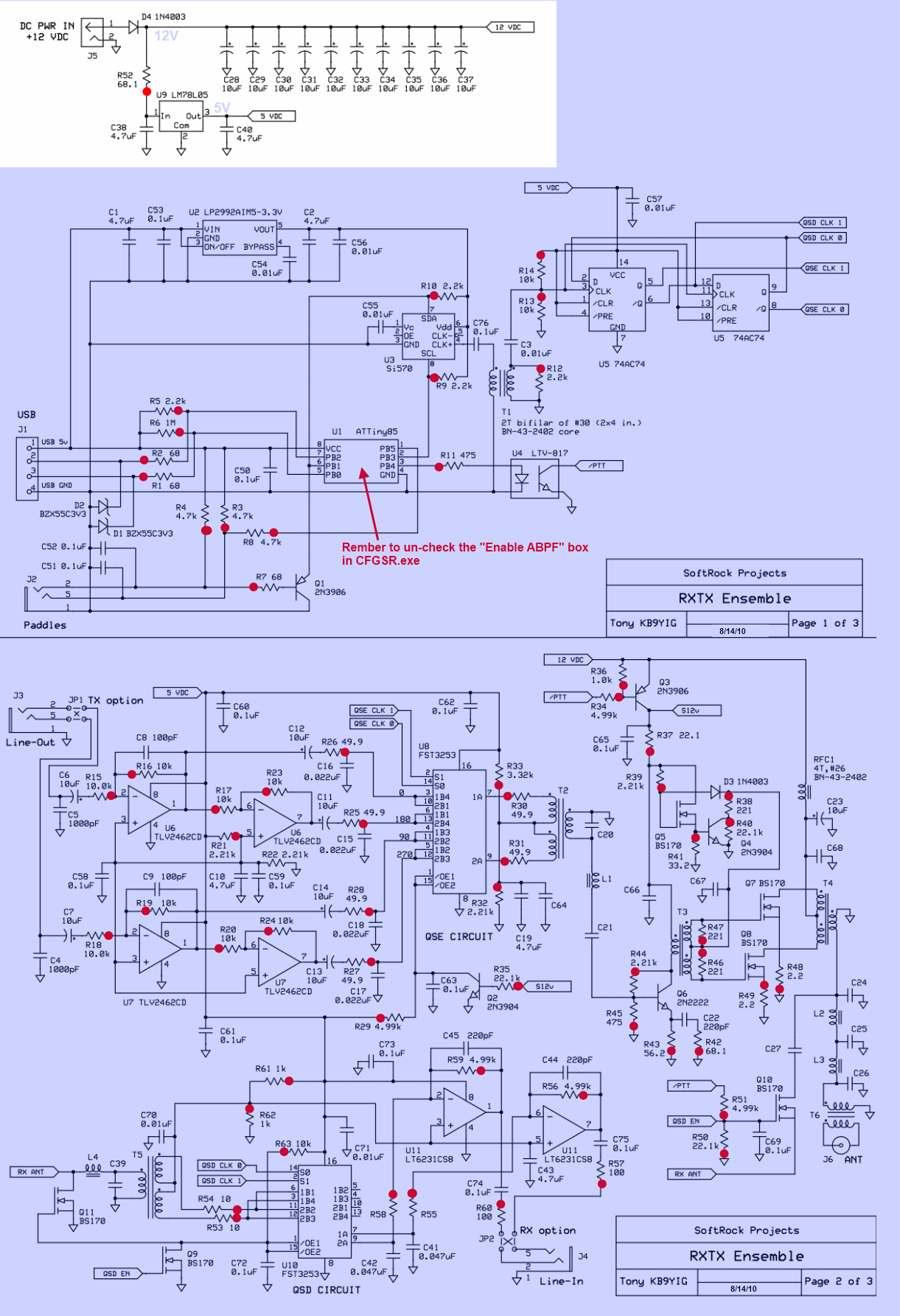
This stage provides the +5 volt power rail for the radio. The incoming voltage (from 9 - 12 Vdc) is regulated by U1 to a nominal 5 Vdc (4.5 - 5.1 Vdc range). D1 serves to protect the circuit from accidentally reversed polarity.
This stage supplies the "regular" 5 volt power rail, for powering the CMOS chips on the main part of the board.
Note: throughout these notes, they will refer to the board in terms of:
- Topside: the side where one can read the silk-screened component designations and outlines
- Bottomside: the reverse of topside, where the SMT components are installed
- Bottom or "bottom edge": the edge of the board where all of the connectors are located
- Top or "top edge": the edge of the board opposite of the bottom edge
Unlkess otherwise noted, all photos/graphics of the board layout are displayed herein with the top edge UP.
Summary Build Notes
Stage Schematic
Go to Top of Page
Click here for full schematic
Board Layouts
Board Top

Go to Top of Page
Board Bottom

Go to Top of Page
Power Supply Bill of Materials
(HF band option)
(details for installation of each component are provided in the step instructions, further down the page)
| Check | Type | Category | Component | Count | Marking | Image |
|---|---|---|---|---|---|---|
| ☐ | boardhdw | HDW | 4 X #4-40 hdw (nut, bolt, washer, spacer) | 1 |
|
|
| ☐ | Capacitor | Ceramic | 4.7 uF 10% 16V X7R RAD | 2 | 475 |
|
| ☐ | Connector | Jack-RA | DC Power Jack PCB Mount (rt-angle) 2.5mm | 1 |

|
|
| ☐ | Connector | Plug | DC Power Plug 5.5/2.5mm Pos Ctr | 1 |

|
|
| ☐ | Diode | Axial | 1N4003 | 1 | 1N4003 Rectifier Diode |
|
| ☐ | IC | TO-92 | LM78L05 voltage regulator | 1 | LM78L05 ESD!!! |

|
| ☐ | PCB | Main Board | Ensemble RX PCB (board) | 1 | ||
| ☐ | Resistor | 1/6W | 68 1/6W 5% | 1 | bl-gry-blk-gld |

|
| ☐ | wire | Cutoff | shunt wire (cut-off lead) | 1 |
Go to Top of Page
Detailed Build Steps
Step_Install Power Supply Components
Install the Diode with the lead on the cathode (banded) end forming a hairpin lead and the anode end snugged up against the board.
| Check | Designation | Component (top/bottom) | Orientation | Marking | Image | Band | Notes |
|---|---|---|---|---|---|---|---|
| ☐ | mtg_hdw | 4 X #4-40 hdw (nut, bolt, washer, spacer) (top) |
|
any | Four each of 3/8 inch 4-40 Phillips head screws,4-40 nuts, 1/8 inch long #4 nylon spacer and #4 nylon washer. Install so spacer is at top of board. 1 3/8" screw, 1 nut, 1 nylon washer, and 1/18" nylon spacer (4 each) |
||
| ☐ | PCB | Ensemble RX PCB (board) (top) | any | Ensemble RX III fivedash.com 6/30/14 |
|||
| ☐ | U06 | LM78L05 voltage regulator (top) | LM78L05 ESD!!! |
|
any | ||
| ☐ | C04 | 4.7 uF 10% 16V X7R RAD (top) | horiz | 475 |
|
any | |
| ☐ | C05 | 4.7 uF 10% 16V X7R RAD (top) | vert | 475 |
|
any | |
| ☐ | R14 | 68 1/6W 5% (top) | S-N | bl-gry-blk-gld |
|
any | |
| ☐ | D3 | 1N4003 (top) | 1N4003 Rectifier Diode |
|
any | Install the Diode with the lead on the cathode (banded) end forming a hairpin lead and the anode end snugged up against the board.
|
|
| ☐ | J03 | DC Power Jack PCB Mount (rt-angle) 2.5mm (top) |
|
any | 2.5mm ID | ||
| ☐ | P1 | DC Power Plug 5.5/2.5mm Pos Ctr (top) |
|
any | Plug furnished with red and black leads. |
Go to Top of Page
Step_Install /RX EN (Ground Point for Regular Ground)

Use a good strong piece of wire, as this will be used as a ground connection point for a number of tests throughout the build.
| Check | Designation | Component (top/bottom) | Orientation | Marking | Image | Band | Notes |
|---|---|---|---|---|---|---|---|
| ☐ | /QSD EN | shunt wire (cut-off lead) (top) | any | (used for regular GND connection point) |
Go to Top of Page
Completed Photos
Note: the completed pictures are of the 40m option, which the author built. Other band options (which the author did not build) will appear slightly different (especially the inductors, whose windings and cores will vary by band) for the band-specific components.
Also note that this board was a pre-production board and some component placements are slightly different from those on the production boards.
View of Completed Topside
View of Completed Underside

Go to Top of Page
Progressive Schematic
Where are we in our progress towards the finish line? Click here to view the entire schematic with the completed stages shaded in a yellowish tinge and the remaining stages tinted in blue (the current stage is untinted).
Test the Power Supply Stage
Power Supply - Current Draw
Measure the resistance (after the input diode) on the power input to ensure there is no short circuit. Measurement can be taken from the hairpin of D3 and the "/QSD EN" ground wire and should read in the Megohm range.
If the measured input resistance is within reason, measure the current draw with your mA meter inserted in series into the positive power lead.
See Tutorial on Measuring Current for an illustration of how to measure current in a circuit.
If you prefer to do so using a current limiting resistor, use something in the 1k-2k range and use ohms law to calculate the maximum current draw to expect for a direct short. Anything considerably lower than that maximum current draw would suggest there was no short
Go to Top of Page
Test Steps (if any)
| Step | Test Point | UOM | Nominal | Author's | Builder's |
|---|---|---|---|---|---|
| 1 | D3 hairpin lead (WRT GND - "/QSD EN") | ohms | > 1M | 7 M and rising | |
| 2 | Current Draw | mA | < 8 | 2.2 |
Go to Top of Page
Power Supply - Voltage Test
With 12 V dc applied to the board (author's gel cell was at 12.19 Vdc), measure the voltage after D3 and measure the output of U7 (the 5 Vdc rail)
Measurements are with respect to (WRT) the regular ground plane (i.e., the non-USB side) of the board.

Go to Top of Page
Test Steps (if any)
| Step | Test Point | UOM | Nominal | Author's | Builder's |
|---|---|---|---|---|---|
| 0 | At Cathode (hairpin) of D3 (WRT regular ground) | Vdc | 11.4 | 11.6 | |
| 1 | At hole for R29 hairpin lead (WRT regular ground) | Vdc | 5 | 5.1 |
Go to Top of Page