Ensemble RXTX - Local Oscillator
Band: 30, 20, 17m
Introduction
You might be interested in watching George Thomas' HamNation presentation of building this stage (presentation begins at 37:00 into the video). Of particular interest is the use of solder paste and an embossing gun to install the SMT parts and his demonstration of winding and installing the isolation transformer, T1.
General Info About the Stage
This stage introduces the microcontroller that controls the programmable Si570 oscillator (as well as handle the paddle input and provide ptt signaling for switching functions.
Note (19 MAR 2019): Roger, Ve7VV, has a very nice PDF that describes the latest approach to installing the software infrastructure
Note: by-pass capacitor C55 is no longer required
Theory of Operation
There are two components to this theoretical discussion: hardware and software
Hardware
The hardware part is fairly straight=forward. The two primary components installed here are the ATTINY-85 microcontroller (a USB device) and the Si570 Programmable Oscillator The microcontroller, reacting to signals from the PC, puts the Si570 through its paces. Actions include configuring the Si570 for operation and, of course, setting its output frequency to a desired value (which is 4 times the desired "center-frequency" of the radio). The Si570 can also respond to status inquiries from the microcontroller. The output of the Si570 is provided to the "radio" side of the radio via the isolation transformer, T1.
In addition, this stage provides the PTT control (from the microcontroller) to optoisolator U4, crossing the galvanic boundary between the USB side and the "radio" side. Finally, this stage includes the circuitry that provides dot/dash inputs from an external paddle to the microcontroller (and, thence, to the PC, where, if the SDR program implements an electronic keyer function, the dot and dash inputs are converted into appropriate streams of dots and dashes).
SDR Software Architacture

The above diagram illustrates the various pieces and their places in the SDR Software architecture. The Radio's critical functionality is provided via the SDR Program. Examples of this include Rocky, HDSDR, SDR#, PowerSDR, PowerSDR-IQ, and others. Each program has its plusses and minuses and it is up to the builder to decide which to use.
The SDR program needs a was to tell the hardware's LO what it should do. There is normally an intermediary piece of software (a "dll") that provides the interface between the SDR software and another (very low level) piece of software called a driver. In the Ensemble's case, the driver is a variant on the "libUSB"
USB driver. The microcontroller on the Ensemble (ATTINY-85) is a computer which "looks like" a USB device to the PC. This is where the USB driver comes in. Every USB device needs some sort of driver that allows the PC's operating system to "recognize" the USB device. The ATTINY-85 is no exception.
The dll talks to the USB device (ATTINY-85) through the USB driver.
The ATTINY-85 then reacts to the signals "delivered" via the PC's USB port into which the cable is plugged. The USB signals (Data+ and Data-) are translated by the ATTINY-85 (running the "firmware" that is pre-loaded into the device) into signals that are recognized by the Si570. Since the USB bus is bi-directional, the Si570 can communicate status back to the PC. Similarly, the ATTINY-85 can send hi/lo signals to the opto-isolators controlling things like PTT (on the RXTX) or Band Switching (on the RX) and can receive dash and dot input lines from an attached paddle.
Summary Build Notes
Stage Schematic

Go to Top of Page
Click here for full schematic
(Red dots represent the "hairpin" (or left-hand or topmost) lead of the component)
Board Layouts


Local Oscillator Bill of Materials
(30, 20, 17m band option)
(details for installation of each component are provided in the step instructions, further down the page)
Be sure to use the correct wire gauge when winding inductor(s)
| Check | Type | Category | Component | Count | Marking | Image |
|---|---|---|---|---|---|---|
| ☐ | Capacitor | SMT 1206 | 0.01 uF | 1 | (smt) no stripe |

|
| ☐ | Capacitor | Ceramic | 0.01 uF | 1 | 103 |

|
| ☐ | Capacitor | SMT 1206 | 0.1 uF | 4 | (smt) black stripe |

|
| ☐ | connector | Socket | socket, machine, 8 pin | 1 |

|
|
| ☐ | Connector | Jack-RA | 3.5mm stereo jack - PCB mount (rt-angle) | 1 |

|
|
| ☐ | Diode | Axial | BZX55C3V3 3.3V zener diode | 2 | BZX55C |

|
| ☐ | IC | DIP 8 | ATtiny 85-20 PU w/V15.12 Firmware | 1 | AVR ATTINY85-20PU ESD!!! |
|
| ☐ | IC | DIP-4 | LTV-817 Opto-Isolator | 1 | LTV 817 ESD!!! |

|
| ☐ | IC | I2C | Si570 Programmable Oscillator | 1 | SiLabs 570 ESD!!! |
|
| ☐ | inductor | Binocular core | BN-43-2402 (no markings!) | 1 | none |

|
| ☐ | Inductor | Xfrmr | 2T Bifilar #30 on BN-43-2402 | 1 | (magnetic wire) | |
| ☐ | Resistor | 1/6W | 68 1/6W 5% | 3 | bl-gry-blk-gld |

|
| ☐ | Resistor | 1/4W | 475 1/4W 1% | 1 | y-v-grn-bl-br |

|
| ☐ | Resistor | 1/6W | 2.2k 1/6W 5% | 4 | red-red-red-gld |

|
| ☐ | Resistor | 1/6W | 4.7k 1/6W 5% | 3 | yel-vio-red-gld |

|
| ☐ | Resistor | 1/6W | 1 M 1/6W 5% | 1 | brn-blk-grn-gld |

|
| ☐ | Transistor | TO-92 | 2N3906 PNP transistor | 1 | 2N3906 |
|
Go to Top of Page
Detailed Build Steps
Step_Install SMT Components
ATTENTION:C55 on pin 1 of the Si570 needs to be removed to comply with the NO CONNECT for this pin for the Si570 supplied with the various kits. Having this capacitor mounted on the circuit board degrades the performance of the RXTX transceiver, especially the higher frequency builds of this kit.
Soldering the Si570 must be carefully done Many builders have encountered problems and, in most cases, they are attributable to improper soldering of the Si570 to the (rather tight) pads. Pay special attention to pads for pins 7 and 8, which are quite narrow. These tend to be the biggest source of soldering problems (e.e., solder bridges). (See helpful video, below, from Alan W2AEW):
| Check | Designation | Component (top/bottom) | Orientation | Marking | Image | Band | Notes |
|---|---|---|---|---|---|---|---|
| ☐ | C50 | 0.1 uF ((bottom)) | (smt) black stripe |
|
any | ||
| ☐ | C51 | 0.1 uF ((bottom)) | (smt) black stripe |
|
any | ||
| ☐ | C52 | 0.1 uF ((bottom)) | (smt) black stripe |
|
any | ||
| ☐ | C55 | 0.01 uF ((bottom)) | (smt) no stripe |
|
any | ATTENTION: Do not install C55, per this note from FiveDash.com: C55 capacitor on pin 1 of the Si570 needs to be removed to comply with the NO CONNECT for this pin for the Si570 supplied with the various kits. Having this capacitor mounted on the circuit board degrades the performance of the RXTX transceiver, especially the higher frequency builds of this kit. |
|
| ☐ | C76 | 0.1 uF ((bottom)) | (smt) black stripe |
|
any | Added 4/4/10 | |
| ☐ | U03 | Si570 Programmable Oscillator ((bottom)) | SiLabs 570 ESD!!! |
|
any |
Go to Top of Page
Step_Install USB Control Components
| Check | Designation | Component (top/bottom) | Orientation | Marking | Image | Band | Notes |
|---|---|---|---|---|---|---|---|
| ☐ | C03 | 0.01 uF (top) | 103 |
|
any | ||
| ☐ | D1 | BZX55C3V3 3.3V zener diode (top) | BZX55C |
|
any | 3.6V Zener | |
| ☐ | D2 | BZX55C3V3 3.3V zener diode (top) | BZX55C |
|
any | 3.6V Zener | |
| ☐ | Q01 | 2N3906 PNP transistor (top) | 2N3906 |
|
any | ||
| ☐ | R01 | 68 1/6W 5% (top) | N-S | bl-gry-blk-gld |
|
any | |
| ☐ | R02 | 68 1/6W 5% (top) | N-S | bl-gry-blk-gld |
|
any | |
| ☐ | R03 | 4.7k 1/6W 5% (top) | W-E | yel-vio-red-gld |
|
any | |
| ☐ | R04 | 4.7k 1/6W 5% (top) | W-E | yel-vio-red-gld |
|
any | |
| ☐ | R05 | 2.2k 1/6W 5% (top) | E-W | red-red-red-gld |
|
any | |
| ☐ | R06 | 1 M 1/6W 5% (top) | E-W | brn-blk-grn-gld |
|
any | |
| ☐ | R07 | 68 1/6W 5% (top) | E-W | bl-gry-blk-gld |
|
any | |
| ☐ | R08 | 4.7k 1/6W 5% (top) | flat-vert | yel-vio-red-gld |
|
any | |
| ☐ | R09 | 2.2k 1/6W 5% (top) | N-S | red-red-red-gld |
|
any | |
| ☐ | R10 | 2.2k 1/6W 5% (top) | N-S | red-red-red-gld |
|
any | |
| ☐ | R11 | 475 1/4W 1% (top) | W-E | y-v-grn-bl-br |
|
any | |
| ☐ | SO01 | socket, machine, 8 pin (top) |
|
any | For ATTin7 85 | ||
| ☐ | U01 | ATtiny 85-20 PU w/V15.12 Firmware (top) |  |
AVR ATTINY85-20PU ESD!!! |
|
any | Mount in socket SO01 PE0FKO V15.12 firmware |
Go to Top of Page
Step_Install Isolation Transformer
Inductor Information
Common Techniques:
- Wire Gauge: remember the higher the number, the thinner the wire. E.g., #30 wire is thinner than #26 wire.
-
One turn:
- For toroids, one turn is a single pass through the center hole.
- For binocular cores, one turn is a pass in which the wire goes in the bottom, comes out the top, goes back in the other hole at the top, and comes out the other hole at the bottom.
- Bi (tri) filar means 2(3) equal lengths of wire. You get the bi(tri)filar strand by taking the length of wire specified for the primary winding, folding it into half(thirds), twisting it to 3~ twists per inch, and winding it over the primary winding. One end of such a strand will have two(three) leads; the other end will have a "hairpin" bend (and a single lead in the case of tri-filar).
- Multi-filar windings are usually done AFTER the uni-filar winding is done.
- Windings shoud be evenly spaced and ideally made such that the winding covers ~345 degrees of the toroid
- Inductance values given are for the single (uni-filar) winding. They are provided to help verify turn counts and core material selected. It's often reported inductances are higher using the theoretical number of turns as calculated by the manufacturer's windings calculator tool, e.g. http://toroids.info/. Normally though these are not too critical, especially with the LF bands antenna noise will still be seen.
-
Toroid nomenclature provides the outside diameter of the toroid (in hundredths
of an inch - the "30" in "T30-2"), and material code (the "2" in "T30-2").
Color codes used in these kits are:
- 2=Red
- 3=Gray
- 6=Yellow
- 7=White
- 10=Black
- 12=Green (with White on opposite side)
Inductors In This Step
T1XFRMR: 2T Bifilar #30 on BN-43-2402
Primary/Secondary using a total of approximately 5 inches of #30 wire, wind 2 turns , bifilar, on a BN-43-2402 ferrite.Inductance of the single winding (usually the primary) is 5.76 uH.
 Wind and Install the transformer (T1) that couples the Si570 output across the galvanic "border" to the Dividers stage. This requires winding a bifilar (2-wire) length onto a binocular transformer. See the notes at WB5RVZ Transformer Winding Instructions if you are unfamiliar with winding binocular transformers, and refer to the diagram below.
Two turns with the twisted pair and you have a transformer with two windings (each winding corresponding to one of the two twisted single wires).
Each winding (primary and secondary) is two turns. Since the windings are identical in length and number of turns, you can arbitratily pick either one as the primary, with the remaining winding serving as the secondary winding.
(Hint: use an ohmmeter (or other continuity checker) to identify which wire-ends go together to make the ends of a winding.
| Check | Designation | Component (top/bottom) | Orientation | Marking | Image | Band | Notes |
|---|---|---|---|---|---|---|---|
| ☐ | R12 | 2.2k 1/6W 5% (top) | N-S | red-red-red-gld |
|
any | |
| ☐ | T1 | 2T Bifilar #30 on BN-43-2402 (top) |
 |
any | |||
| ☐ | T1-core | BN-43-2402 (no markings!) (top) | none |
|
any |
Go to Top of Page
Step_Install Remaining Topside Components
U4 is oriented with the dot lined up with the barrel of R11 (i.e., the dot is toward the bottom of the board, closest to the left hand edge
| Check | Designation | Component (top/bottom) | Orientation | Marking | Image | Band | Notes |
|---|---|---|---|---|---|---|---|
| ☐ | J2 | 3.5mm stereo jack - PCB mount (rt-angle) (top) |
|
any | |||
| ☐ | U04 | LTV-817 Opto-Isolator (top) | 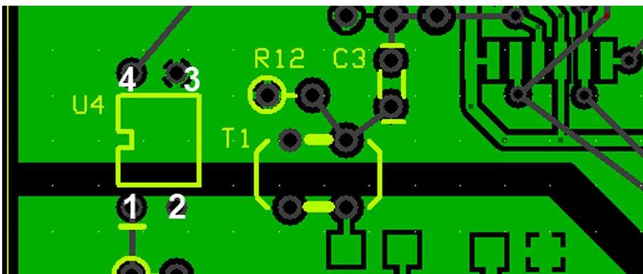 |
LTV 817 ESD!!! |
|
any |
Go to Top of Page
Step_Download and Install Software and Drivers
All of the latest versions of essential firmware configuration programs, USB driver and their associated documentation can be obtained from Fred PE0FKO's website:
- Amateur Radio Certificate Authority
- USB driver: (search for "Download Firmware source and .hex files")
- CFGSR program: (search for "Download")
- Documentation
In order to test (and later, operate) your rig, you must download and install required software (SDR programs and Dynamic Link Libraries, along with hardware drivers. The actual steps and programs may vary, depending upon your computer's windows operating system version (XP, Vista, Windows 7, 8, or 10) and architecture CPU/memory (32 bit or 64 bit). Generally, the process involves the following:
- Install the libraries and drivers (PE0FKO'a "All-In_One" Installer
- Test installation using CFGSR
- When ready to operate, install desired SDR program (e.g., HDSDR, SDR#, Rocky, PowerSDR, etc)
The following links are provided and, as of 1/22/2012, are current. Links highlighted in an Aqua-colored background apply only to those Softrock kits that use the SI570 programmable oscillator:
| Software | Role/Purpose | Function | Download Link | Notes |
|---|---|---|---|---|
| CFGSR | Configure/Control Ensemble microcontroller | Configure | download | See the FiveDash documentation for software installation |
| SRDLL | dll for other Softrock controllers | Control | (now part of CFGSR install file, so no need to go out and find/install it separately.) | |
|
New All-In-One
Driver Installer (See Section Titled "Install the PC driver software automatic" |
New installer for "signed" PE0FKO-USB-Driver from Fred, PE0FKO. | Driver | Download | See the FiveDash documentation for software installation |
| USB driver(s) | drivers for ATTiny85 USB | Driver | download |
Zip file with 32 and 64 bit drivers (latest version is 1.2.6.0)*. Preferred installation method is the "All in One" method depicted above and further described in the FiveDash documentation for software installation . |
| (32/64 bit Windows 7, Vista, XP) PowerSDR-V2.4 For Homemade SDR Transceivers | Latest Version of FlexRadio's PowerSDR tailored for I/Q Soundcard-based SDRs. Click here for installation instructions. | RXTX | download |
Has Si570 Control Capability (
Please see Christos Nikolaou' message 2583 on the PowerSDR-IQ Yahoo Reflector). This
is good for all Windows platforms and handles RX and TX in all modes. All required
software (to include the All-In-One USB Driver Installer) is furnished.
One needs only to download the basic FLex PowerSDR V2.4.4 from
the Flex site) to have a complete software solution.
This is the most comprehensive of all the packages. However, commensurate with its power comes a steep learning curve. |
| SDR # | SDR # ("SDR Sharp") for RX | RX | Download | Very good and simple program (RX only; TX tbd) from Youssef Touil. Alan, G4ZFQ, has a nice article on setting up SDR# for an Ensemble RX II. |
| Rocky (V3.7). (V3.8 has been developed for later Windows versions) | Simple SDR (RX/TX) Program (see note below) | RXTX | download | SSB RX, CW and PSK-31 RXTX. Great little Windows-based program (but it has hsd its issues with more modern versions of Windows - soundcards. The later version of Rocky - V3.8 - addresses many of these issues.). |
| HDSDR (V2.7) | Elegant SDR (RXTX) Program (based upon original Winrad) | RXTX | download | CW is very basic and only properly useable on the older 6.3 Softrocks. For installation and setup info, see: these pages from Alan, G4FZQ. Also, see the FiveDash documentation for software installation |
| (Windows XP) PowerSDR-IQ V1.12.20 | Version of FlexRadio's PowerSDR tailored for I/Q Soundcard-based SDRs | RXTX | download |
Has Si570 Control Capability.
Based upon recent experience, the PowerSdr v2.4 above is recommended in lieu of this version. |
| (Windows 7, Vista) PowerSDR-IQ V1.19.3.15 | Earlier version of FlexRadio's PowerSDR tailored for I/Q Soundcard-based SDRs | RXTX | download |
Based upon recent experience, the PowerSdr v2.4.4 above is recommended in lieu of
this version.
Has Si570 Control Capability (Please see Christos' message 43204 on the Yahoo Reflector) |
| com0com | An open source null modem/virtual serial port manager | Utility (VSP) | Com0com is useful for interfacing third-party CAT-based software (e.g., HRD, FLDIGI, etc.) with PowerSDR or other CAT-capable SDR programs. Christos Nikolaou, SV1EIA, has provided this signed version of com0com's installation file for Windows 7 64 bit OS (which requires a signed version). | |
| VAC | Virtual Audio Cable - a software audio "patch cable" | Utility (VAC) - Free trial (but don't use trial on the air!) | Website for download: http://software.muzychenko.net/eng/vac.htm | VAC is indispensible when attempting to interface thrird party programs (e.g., HRD, FLDIGI, etc.) with SDR Programs. It allows us to "patch" audio to and from the soundcard to another program. |
Install Driver
To be extra safe, it is highly recommended that you install the drivers with no other USB devices connected directly to your PC during the install. If your mouse and/or keyboard are USB, reconnect them through a USB hub. This seems to help avoid the dreaded "Unknown Device" Problem.
If you do not use the All_in_One Installer from PE0FKO, the correct procedure is to download the driver and put it in a suitable folder, then plug in the USB lead, Windows should detect new hardware has been found and you need to manually point it to the folder containing the drive. It should then install correctly. Certainly does on Win2000 and XP. On Vista or Windows 7, there used to be some issues with driver signing. There have been messages on the forum describing methods of working around these issues. One such solution is addressed in the author's MOBO4.3 builders notes.
LibUSB - "Unknown Device" Error
Others have experienced the dreaded "Unknown Device" problem upon plugging in the USB cable after having installed the LibUsb driver. This "unknown device" problem (and a remedy for those who are using Logitech cordless mouse and/or various wireless internet connection adaptors) are discussed in message #45071 and Message #47755 on the Yahoo Softrock40 Group
Another valueable resource for troubleshooting the "unknown device" error is Alan's webpage Installing the ATTiny45/85_USB Controller
Install/Run CFGSR ("ConFiGureSoftRock") (automatically installed in All-In_One Installer)
Once the driver is installed, if you run 'CFGSR' that will either automatically 'open' the firmware, or if not, you need to go to the 'USB' tab and select it from the list displayed in the bottom box. Which way depends on if you have 'CFGSR' set up to auto connect on program start or not.
Following configuration with CFGSR, it is adviseable to use one of the simpler SDR programs for initial testing of RX (and/or TX) functionality, even though you may want to have a more robust piece of software as your ultimate radio.
For further discussions of the software side of SDR and soundcard issues, see Alan G4ZFQ's pages.
Test Local Oscillator Using CFGSDRr
You can use 'CFGSR' to exercise the Si570 using the 'Tune' tab that makes it into a 'VFO'. Just a case of setting the frequency, and the Si570 should output a signal at 4 times the frequency displayed on the main display on the screen. Tuning can be done either by typing in the frequency or by using the mouse wheel to change the frequency by increments ranging from 1kHz to 10 MHz.
The 'Test' tab can also be used to look at all the various Si570 registers etc, but probably unnecessary as if you can hear or measure the Si570 output frequency, you know it is working.
Optionally, Install SD Program
You may, if you wish, install the SDR program of your choice here (e.g., HDSDR, Rocky, SDR#, etc.). However it is not necessary until the final stage of the build project, when you test out the receiver.
usbsoftrock" [Linux]:There is also a usb driver for Linux platforms. it's no longer available from the Google Code repository, but is still available in various Linux distros and in Alex Lee's github repo at https://github.com/alexlee188/usbsoftrock-alex
Note (19 MAR 2019): Roger, Ve7VV, has a very nice PDF that describes the latest approach to installing the software infrastructure
Disable ABPF
Experienced builders often hit the case where the TX seems "locked" in transmit mode. This is almost always caused by leaving the ATTINY85 configured for Auto Band Switching. You must un-check the "Enable ABPF" box in CFGSR.EXE.
it is essential before any functional tests are carried out, as soon as you have the PC talking to the Ensemble using the USB interface is to use 'CFGSR' and go to the 'ABPF' tab and remove the check from the 'Enable Filter (ABPF) box. You must then unplug and reconnect the USB lead in order to reinitialise the AVR chip so it has the PTT and CW key functions enabled. If you do not do this, the AVR chip is supplied with the defaults set for use with the v9.0 RX and BPF module, so will catch a lot of people out, in the same way as the USB to I2C interface has.
Test Paddles
In 'CFGSR' if you select the 'Test' tab, and check the 'Repeat' box, there are three LEDs at the bottom of the screen that display the status of the PTT, CW1 and CW2 lines. You can exercise the CW1 and CW2 key inputs and you will see the LEDs change.

For further discussions of the software side of SDR and soundcard issues, see Alan G4ZFQ's pages.
PSDR Issues
There is a lively discussion of the issues in setting up Power SDR (various versions) for the Softrocks at the thread for Message #47707 in the Softrock40 reflector. WB5RVZ has also posted some guidelines in setting up PSDR for the Vista (and supposedly, Win 7) environment..
Go to Top of Page
Completed Photos
View of Completed Topside
View of Completed Underside
Go to Top of Page
Progressive Schematic
Where are we in our progress towards the finish line? Click here to view the entire schematic with the completed stages shaded in a yellowish tinge and the remaining stages tinted in blue (the current stage is untinted).
Test the Local Oscillator Stage
Local Oscillator - LO Stage Outputs
Here we want to measure the outputs (4x center frequency for dividers and /PTT signals for PTT/RX switching). They are measured WRT (regular) ground (at the R50 hairpion lead).
Setup
Be sure all software and drivers, etc., have been installed. Connect the USB jack via USB cable to the PC. You should hear the "BoopBoop" sound the PC makes when it recognizes a device (the Ensemble) has been attached to a USB port..
Next, run CFGSDR.exe and you should get the following screen:

Then, check out the "Si570" tab. It should look like this:

Note that the Local Oscillator's outputs are measured with respect to the analog ground plane, NOT with respect to the galvanically isolated USB groundplane
Using the CFGSR Software (at the "Tune" tab), test scenarios for setting the center frequency (remember, the Si570 produces a signal that is 4 times the desired center frequency) and PTT on/OFF. Measure the outputs at the points indicated as "LO Out" and "/PTT". Below is an example of tuning the Si570 in CFGSR, selecting a center frerquency of 6.05 MHz (with an Si570 output frequency of 4x, or 24.2MHz. (Pay no attention to the lousy oscilloscope behind the curtains - the output is really a square wave, but the scope is a cheap USB scope that doesn't sample HF square waves very well.)

You can place your mouse on the frequency in the center frequency field and turn your mouse wheel. The center frequency will increase or decrease and the LO Output frequency (4x) will increase or decrease at a rate 4 times that of the center frequency.
John, KB6QL, discovered this trick for those with no scope, counter, or HF radio to use in testing LO output:
"Turns out that local oscillator can be tuned for a frequency that is in the FM band. So, as a quick and dirty, I got out my little MP3 player-cum-FM-radio and tuned it to that frequency and let the headset cord/ant drape over the RXTX. It gave me full quieting. Then I switched the RXTX to another frequency and the quieting was gone."
Troubleshooting Hints
Device Not Recognized
If your computer does not recognize the ATTiny 85 device, the cause could be either hardware or software.
Hardware
In many cases, this can be attributed to the way Windows handles USB devices. A common solution is to disconnect all USB devices and then connect the Ensemble's USB cable first. Another way is to leave the Ensemble plugged in and reboot the computer with the Ensemble cable still connected. This will deal with Windows' inability to uniquely identify the USB device from among competing, simiar devices.
Check the resistors (R1-R4) and make certain they are the correct value
Check the alignment and placement of U1 and make sure it is snugly fitting in the socket. It is easy to accidentally bend one or more of the pins when inserting the chip into the socket.
Cecil K5NWA suggests:"Check for solder shorts, chips in backwards, power problems, make sure the diodes in the USB lines are not backwards."
Software
Review the WB5RVZ software "schematic" and then:
Check out Alan G4ZFQ's great webpage on Si570/ATTiny85 issues.
Si570 Does Not Respond to Control Signals

Soldering on the Si570 is the most usual problem with lack of control, providing the USB is properly recognised.
Frequency Will Not Change
If the LO oscillates at the factory default frequency but will not respond to your attempts to change the frequency, the very first place to look is on the soldering of the Si570, most especially pins 7 and 8. Those pins - and their soldering - constitute the single most often found cause of inability to change the frequency of the Si570.
Go to Top of Page
Test Steps (if any)
Go to Top of Page
Local Oscillator - Opto-Isolator Voltage Test
Power up the board in (default) RX mode
Measure the voltage at pin 1 of the OptoIsolator
Pin 1 of the isolator should be less than 0.5 volts with respect to pin2 (the isolated USB, not regular, ground).
Go to Top of Page
Test Steps (if any)
| Step | Test Point | UOM | Nominal | Author's | Builder's |
|---|---|---|---|---|---|
| 1 | U4-Pin 1 (WRT USB Ground) | Vdc | < 0.5 | tbd |
Go to Top of Page