Test the Power Supply Stage
Return to Power Supply
Power Supply - Current Draw
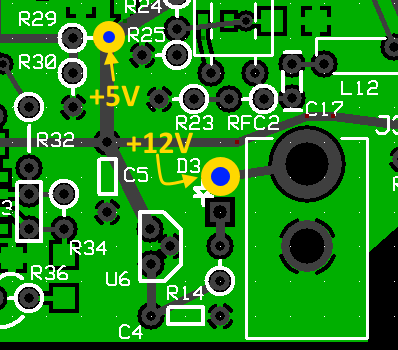
Measure the resistance (after the input diode) on the power input to ensure there is no short circuit. Measurement can be taken from the hairpin of D3 and the "/QSD EN" ground wire and should read in the Megohm range.
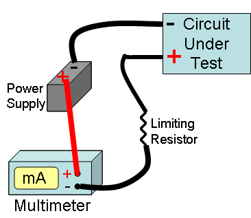
If the measured input resistance is within reason, measure the current draw with your mA meter inserted in series into the positive power lead.
See Tutorial on Measuring Current for an illustration of how to measure current in a circuit.
If you prefer to do so using a current limiting resistor, use something in the 1k-2k range and use ohms law to calculate the maximum current draw to expect for a direct short. Anything considerably lower than that maximum current draw would suggest there was no short

Test Steps (if any)
| Step | Test Point | UOM | Nominal | Author's | Builder's |
|---|---|---|---|---|---|
| 1 | D3 hairpin lead (WRT GND - "/QSD EN") | ohms | > 1M | 7 M and rising | |
| 2 | Current Draw | mA | < 8 | 2.2 |
Power Supply - Voltage Test
With 12 V dc applied to the board (author's gel cell was at 12.19 Vdc), measure the voltage after D3 and measure the output of U7 (the 5 Vdc rail)
Measurements are with respect to (WRT) the regular ground plane (i.e., the non-USB side) of the board.


Test Steps (if any)
| Step | Test Point | UOM | Nominal | Author's | Builder's |
|---|---|---|---|---|---|
| 0 | At Cathode (hairpin) of D3 (WRT regular ground) | Vdc | 11.4 | 11.6 | |
| 1 | At hole for R29 hairpin lead (WRT regular ground) | Vdc | 5 | 5.1 |