Test the USB Power Supply Stage
Return to USB Power Supply
USB Power Supply - Test Resistances
Measure resistances on the power rails to be sure there are no short circuits.

Test Steps (if any)
| Step | Test Point | UOM | Nominal | Author's | Builder's |
|---|---|---|---|---|---|
| 0 | (A) 3.3V rail: R7 barrel to USB Grnd (G) | ohms | >100k | 130k | |
| 2 | (B) USB 5V rail: R4 barrel to USB Ground (G) | ohms | > 1M | 7M and rising |
USB Power Supply - Voltage Test
Connect the USB cable to the PC and to the board.
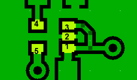
Measure the USB voltages (with respect to the USB ground) at the points indicated on the graphic
Note the two test points are the BARREL ends, not the hairpins, of the resistors (which do not get installed until the next stage).
TroubleShooting the 3.3V Regulator
One case was reported where the regulator tested approximately 1.8 V (as opposed to 3.3V). This was determined to be a faulty bypass capacitor (C32) bypassing pin 4 of the regulator to USB ground).
In another similar case, the problem was due to a nearly invisible solder "whisker"/bridge between two of the pins on the three-pin side (recall that the center pin (#2, below) of the three is ground!)


Test Steps (if any)
| Step | Test Point | UOM | Nominal | Author's | Builder's |
|---|---|---|---|---|---|
| 0 | 3.3V point R8 (BARREL end - WRT USB Ground) | Vdc | 3.3 | 3.29 | |
| 1 | USB 5V: R4 (BARRELL end - WRT USB Ground) | Vdc | 5 | 5.15 |