Ensemble RXTX - Home Page
Band: 30, 20, 17m
This is the successor website (wb5rvz.org) for the Ensemble RXTX, originally documented on the wb5rvz.com site
'''''''''''''Introduction
General Info
Announcement - Official Site
This site is now the officially maintained site for the Ensemble RXTX kit. The previous documentation on www.wb5rvz.com is no longer being maintained. If you are curious, you can still pop over to the previous site to see the original documentation, but be advised that it is no longer being maintained there.
These notes were developed as the author built the pre-production version of the kit (4/4/2010), resulting in some minor rearrangements of layouts. These will cause the "completed" pictures at the end of each stage to be slightly different, due to the layout changes between that version and the currently documented production version.
This kit is an SDR Transceiver that follows in the very successful line of RXTX Softrocks, the most recent being the RXTX V6.3 multi-band transceiver. The Ensemble kit is essentially the RXTX V6.3, but with its band-specific components fixed and predetermined (as opposed to the plug-in daughtrer boards for these functions in the RXTX V6.3). The kit, therefore, is not compatible with the Mobo series of add-ons, since they depend upon the plug and socket arrangements of the RXTX V6.3. The kit comes in five versions, corresponding to five "super-bands":
- 160m - covering the 160m band
- 80m, 40m - covering the 80 and 40 meter bands
- 40m, 30m, 20m - covering the 40 through 20 meter bands (added 7/12/2010)
- 30m, 20m, 17m - covering the 30, 20 and 17 meter bands
- 15m, 12m, 10m - covering trhe 15, 12, and 10 meter bands
What band to Choose? If you are not certain of which band option you wish to build, check out the discussion in this thread on the Yahoo Softrock40 reflector.
Once you have decided on your band choice, you can select the band by clicking on the "Bands" tab at the top of any page on the Ensemble RXTX website. This will customize these notes (and theid component values) for the selected band option. The band selection will hold for the duration of your "session" on the website and while in the Ensemble RXTX portion. Get in the habit of checking the header on each page to be sure your band selection is still in effect.
In each version, the radio has complete frequency agility within the "super-band" (thanks to the reliable Si570 programmable oscillator), limited only by the fixed/installed band-specific components. This means that, for example, with the 30/20/17m version, the user can operate all modes on all three of those ham bands, anywhere in those bands, subject only to the limitations of their license and the SDR software being used. In fact, the kit can also receive any HF signals within the installed "super-band".
The kit provides an Atmel AVRMicrocontroller on-board, programmed to act as a USB device and installed in a galvanically isolated section of the board. Achange from the earlier transceivers is the addition of jumpers on board to switch the ring and tip assignments of RX and TX I and Q signals.
Another welcome change from the earlier models is that all connections to the outside world are handled via on-board jacks (provided with the kit).
The kit is offered with all of the parts necessary to build it for any one of the five possible versions. Consequently, the builder will always have some parts "left-over" at the end of the build. These documents contain band-specific Bill of Materials listings for each version (in addition to the Bill of Materials for the parts of the radio that are not band-specific.
One Builder's Experience - Bill Fahle K5WL
Availability
Tony Parks has released the following information concerning availability and pricing of this kit (message dated 5/21/2010):
Recent test results with RXTX Ensemble prototype units gives me confidence that the kit is ready for production. Later today 200 circuit boards will be placed on order so that 200 kits can be made available starting the second week of June.
The RXTX Ensemble kit will include all components so that the kit may be built as a one watt SDR transceiver for one of four band groups: 160m, or 80m/40m, 40m/30m/20m, or 30m/20m/17m, or 15m/12m/10m.
The kit price is $89 plus $3 for US postage or $6 for DX postage. DX kit mailing will be made in two padded envelopes to keep the value of each envelope low. (The $89 kit price compares well to the total price of $84 for the equivalent functions in the v6.3 RXTX.)

You can order this kit on the FiveDash website.
You should read through these instructions thoroughly before commencing the build. As a convenience, should you like to use it, there is a page that provides a very abbreviated list of build notes for each stage, along with the relevant topside and bottomside board layouts. You could run that page and print it out for use during the actual build of the stage.
Theory of Operation
Alan, W2AEW, has produced an excellent, short, but very educational video on how I and Q signals in an SDR can provide just about any kind of RF modulation/demodulation you could imagine. Well worth the short viewing:
Refer to the block diagram below
(click on any block in the diagram to go to the build stage which implements that block)

Foundation Circuitry
The transceiver is controlled by an Attiny85 microcontroller, programmed as a USB device to provide PTT control, paddles input, and local oscillator frequency control, in a galvanically isolated area of the PCB.
Power (+5 Vdc) for this section is provided by the USB bus from the PC. Power for the programmable local oscillator is provided by converting the USB bus power down to 3.3 Vdc (in the USB Power stage).
The function of the local oscillator is to produce a signal whose frequency is four times the desired "center frequency" of the radio. The "center frequency", plus the sound card in the PC, will determine the width of the "chunk of spectrum" one will see in the RX (and TX) display on the PC's screen - i.e., the available, visible bandwidth. This bandwidth is represented as a number of kHz either side of the "center frequency. That number of kHz is half of the sound card's sampling rate. Normal sampling rates are 48 kHz, 96 kHz, and 192 kHz (corresponding to bandwidths of the "center frequency" plus or minus 24 kHz, 48 kHz, and 96 kHz, respectively. The sampling rate of the sound card is directly proportional to the cost of the sound card - the higher the rate, the higher the cost.
The output of the local oscillator is fed to the dividers stage, where the signal is divided by 4, yielding two signals which are identical except that they are 90 degrees out of phase with each other - i.e., in quadrature. These signals are at the "center frequency" and will clock both the RX mixer and the TX mixer.
RX Circuitry
The transceiver has a common antenna terminal and RF path which is switched between the RX Bandpass filters (default) and the TX low-pass filters, via circuitry in the RF I/O and Switching Stage. The switching is performed in response to the /PTT signal from the microcontroller, as selected by the SDR program on the PC. In the RX chain, the incoming RF is band-pass filtered in T5/L4/C39, with the RF output at T5's secondaries in antiphase.
The antiphase RF signals out of T5 are coupled into the RX Mixer Stage via R53 and R54. The mixer chip (actually a commutating switch, clocked by the two QSD Clock signals from the Dividers Stage) outputs the product and difference signals of the incoming RF against the QSD clock. The effect is to down-convert the incoming RF into its quadrature analogues at frequencies ranging from 0 to roughly 100 kHz.
These quadrature pairs from the RX Mixer, identifcal in all respects except phase, are fed to the RX OpAmp Stage for amplification and filtering into the audio and infra-audio range and delivered to the RX output stereo audio jack, J4, to be input to the PC's STEREO input (line-in or Mic).
The PC's sound card performs a conversion of the two analog signals ("I and Q") to a digital representation, which is then operated upon by modules of the SDR program to perform the many "radio" functions, such as demodulation, filtering, AGC, etc., that are expected of a fine receiver. To do this, it absolutely essential that the soundcard being used supports STEREO input. The sampling rate, quality and specs of the soundcard will determine whether and how well the PC can work signals whose frequency is either sode of the center frequency. Common sound card sampling ratesfor this bandwidth are 48 kHZ, 96 kHz, and 192 kHz. These each correspond to the ability to support SDR processing of "chunks" of bandwidth of 48 kHz, 96 kHz, and 192 kHz, each chunk centered on the center frequency (CF), with "wings" on either side of the CF that are one-half the sampling rate in width.
TX Circuitry
The transmit functionality is essentially the reverse of the RX functionality. In the PC, rather than demodulating input I and Q signals as in the RX, the PC modulates the digital signals (from the microphone or a keyer module. for example) into analog I and Q (infra) audio STEREO outputs, typically output to the line-out jack on the soundcard. The I and Q signals at the line-out are in quadrature (identical in all respects save phase) and appear at stereo jack J3. There are fed to the TX OpAmp Stage. This unitary gain stage translates the I and Q signals into four equal signals, at 0, 90, 180, and 270 degrees of phase.
These four signals from the TX Opamp Stage are coupled via R25-R28 to the TX Mixer Stage. Just as the RX Mixers "mixed" incoming RF with the QSD clock (center frequency) signals to produce (infra)audio signals, the TX Mixer does the reverse, "mixing" modulated (infra) audio signals with the QSE RF clock signals to produce up-converted RF outputs that are analogues of the TX I and Q inputs. This modulated RF output of the TX Mixer (aka "Quadrature Sampling Exciter", or "QSE") is coupled via T2, C20, L1, and C21 to the Driver/PA stage.
The Driver/PA stage shapes and amplifies the modulated RF output from the TX Mixer stage and feeds the result to the antenna path as switched by the PTT switching circuitry. The switching circuitry activates the Driver/PA stage and forces a S12 line to high (approximately 12 Vdc), to permit switching an external amplifier. This stage will deliver approximately one watt of output into a 50 ohm load.
For an excellent, simple discussion of the Theory of SDR, see Tobias DH1TW's "do you truly understand the SDR concept?"
Project Schematic
(Resistor testpoints (hairpin, top, or left-hand lead), as physically installed on the board, are marked in the schematic with red dots) (You can review the individual schematic sheets:
sheet1,
sheet 2,
sheet 3
)
(You can review the individual schematic sheets:
sheet1,
sheet 2,
sheet 3
)
Project Bill of Materials
This project will have two different types of 68 ohm resistor: the precision
(one 68.1 ohm, 1/4W and three of the smaller 68 ohm, 1/6 W).
Also, watch out for the different wire sizes: the higher the number, the thinner the wire. Don't mistake #30 for #26 and run out of one or the other
The Ensemble RXTX kit has an extensive Bill of Materials. The kit contains sufficient parts to build any one of the several band-coverage options. To aid the builder throughout the build, the bill of materials will be presented in several different ways:
- Traditional Project Level Bill of Materials - for selected band (click to view)
- Project Level Inventory of Components (regardless of selected band) (click to view)
- Project Level Bill of Materials Cross-Referenced to Stages - for selected band (click to view)
- In addition, each stage will show its own Bill of Materials for the selected band and
- Each step, within a stage, will show its own Bill of Materials for the selected band
Board Layouts
Topside
Underside
(Component colors: BLUE = band-specific; WHITE caps = 0.1 uF SMT - black striped strip; YELLOW caps = 0.01 uF SMT - clear strip)
Expert's (Terse) Build Notes
- Review the schematics sheets: ( sheet1, sheet 2, sheet 3))
- Install Power Supplies (12, 5, and 3.3 Vdc)
- Install Local Oscillator and Dividers
- Install RF Chain and Switching Circuitry
- Install RX: QSD amd OpAmps
- Install TX: Opamps and QSE
- Install Driver/PA
- Install Software and hookup RXTX
Ensemble RXTX Detailed Build Notes
For the non-expert builders among us, this site takes you through a stage-by-stage build of the kit. Each stage is self-contained and outlines the steps to build and test the stage. This ensures that you will have a much better chance of success once you reach the last step, since you will have successfully built and tested each preceding stage before moving on to the next stage.
Each stage is listed below, in build order, and you can link to it by clicking on its name below (or in the header and/or footer of each web page).
- Validate the (band-agnostic) Component Counts for the Kit
- Check the Bill of materials for the Selected Band Option
- Build and Test the Power Supply stage.
- Build and Test the USB Power Supply stage.
- Build and Test the Local Oscillator stage.
- Build and Test the Dividers stage.
- Build and Test the RF I/O and Switching stage.
- Build and Test the RX Mixer (QSD) stage.
- Build and Test the RX Opamps and Output stage.
- Build and Test the TX Opamps stage.
- Build and Test the TX Mixer (QSE) stage.
- Build and Test the Driver/PA stage.
- Build and Test the External Connections stage.
Stage-By-Stage Testing
Each stage will have a "Testing" Section, outlining one or more tests that, when successfully completed, provide you with the confidence and assurance that you are heading in the right direction towards a fully tested and built transceiver.
When you perform a test, you should always record the results of the test where indicated in the Testing section. This will make troubleshooting via the reflector much easier, since you will be communicating with the experts using a standard testing and measurement regime.
When comparing measurements to those published in these notes, the builder should be aware that actual and expected values could vary by as much as +/- 10%. The idea behind furnishing "expected/nominal" measurement values is to provide the builder with a good, "ballpark" number to determine whether or not the test has been successful. If the builder has concerns about his measurements, he should by all means pose those concerns as a query in the Softrock reflector so the experts can provide assistance.
This kit can be built and reliably tested using nothing more than a common multimeter. Tests assume that the builder has a decent digital multimeter of sufficiently high input impedance as to minimize circuit loading issues. Measurements will be taken of current draws, test point voltages, and resistances.
Most stages will have a current draw test, in which the builder tests the stage's current draw in two different ways:
- First, testing the draw through a current-limiting resistor
- Then, when that test is OK, removing the current-limiting resistor and measuring the real current draw.
The IQGen or
DQ-Gen programs
available free from Michael Keller, DL6IAK, can be used in a pinch to get the sound
card to produce audio tones for injection into the circuit.
You can always use Rocky to generate I and Q signals for tests requiring these audio signals (this is the author's preferred way)
Completed Kit - Top View
Completed Kit - Bottom View

Background Info
Tools
Winding Inductors
This page has the following inductors:
- L1
- L2
- L200
- L201
- L3
- L4
- RFC1
- T1
- T2
- T3
- T4
- T5
- T6
To learn how to wind coils and transformers, please read the
- tips from the experts and then
- view the excellent videos on KC0WOXs Website
- or take a read of Dinesh's VU2FD guidelines.
- You can review the common construction techniques for inductors for details on deciphering the winding specifications, core specifications,and construction of toroidal and binocular inductors.
Component Identification
After soldering problems, the most common cause of trouble in kit building is the installation of the incorrect component. Most often this is the case with resistors (hint - if voltage or current draw tests are way out of whack, suspect resistors or solder bridges). Invest in a cheap multimeter and MEASURE the resistance. As Pete, M0FMT, said: " ... then you don't have to worry about this modern trend of poor identification of components. I doubt you will find an issue with Tony's kits but measuring is best. A cheap OVA meter costs 2 or 3 bucks and a simple cap bridge is easy to build. (you can search E-Bay for "L/C/F Inductance Capacitance High Precision Meter" and will find several digital L/C meters for $20-$30) These two bits of kit are worth there wieght in gold. Oh and most meters have diode and transistor testers build in... remarkable when you think back to the darkages when I were a lad."
It cannot be overstressed: do not rely solely on the color codes for identification of the correct resistor; ALWAYS measure with your ohmmeter as a double check. Measure twice, cut once.
Soldering
If you are not experienced at soldering (and even if you are somewhat experienced at soldering), refer to excellent tutorial on basic soldering techniques by Tom Hammond N0SS (SK).
This video provides some excellent hints at soldering (and de-soldering) SMT components:
The video below describes techniques for soldering SOIC 14 (and 16 and 8) SMDs
View the above in full-screen mode on Youtube.
You may also want to review the information from the HamNation series on George, W5JDX, and his build of the Softrock Ensemble RXTX. He uses an inexpensive heat gun and Solder paste to install SMT capacitors and ICs. The Session where he introduces the process is in Episode #70 at 36 minutes, 30 seconds into the podcast.
For the more adventurous, there is a process using solder paste and an electric oven called the reflow process, which can be used to install all the SMT chips to one side of the PC Board. This is documented by Guenael Jouchet in the following Youtube segment:
- Read the Primer on SMT Soldering at the Sparkfun site. It is a very good read and it speaks great truths. Then take the time to watch the video tutorial on soldering an SOIC SMD IC.
- Solder Stations. Don't skimp here. Soldering deficiencies
account for 80 percent of the problems surfaced in troubleshooting. It is preferable
to have an ESD-safe station, with a grounded tip. A couple of good stations that
are relatively inexpensive are:
-
 Velleman VTSS5U 50W Solder Station (approx $25 at Frys) (See BGMicro for Spare Tips)
 -
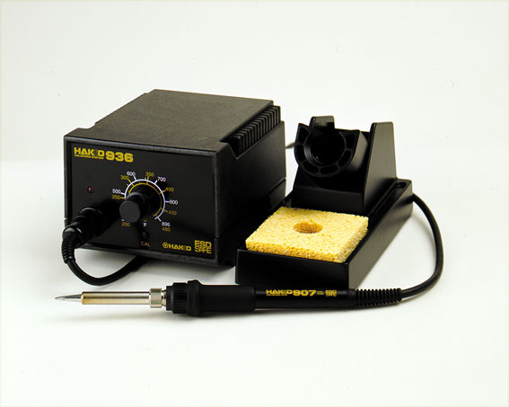 Hakko (Aoyue) 936 ESD Solder Station (under $100)
-
ESD Protection
You may wish to review the message topic beginning at Message 43554 for a common-sense discussion on ESD.
- Avoid carpets in cool, dry areas.
- Leave PC cards and memory modules in their anti-static packaging until ready to be installed.
- Dissipate static electricity before handling any system components (PC cards, memory modules) by touching a grounded metal object, such as the system unit unpainted metal chassis.
- If possible, use antistatic devices, such as wrist straps and antistatic mats (see Radio Shack's Set for $25 or the JameCo AntiStatic mat for $15)).
- Always hold a PC card or memory module by its edges. Avoid touching the contacts and components on the memory module.
- Before removing chips from insulator, put on the wrist strap connected to the ESD mat. All work with CMOS chips should be done with the wrist strap on.
- As an added precaution before first touching a chip, you should touch a finger to a grounded metal surface.
- If using a DMM, its outside should be in contact with the ground of the ESD mat, and both leads shorted to this ground before use.
- See the review of ESD Precautions at this link.
Work Area
- You will need a well-lit work area and a minimum of 3X magnification (the author uses a cheap magnifying fluorescent light with a 3X lens. This is supplemented by a hand-held 10 X loupe - with light - for close-in inspection of solder joints and SMT installation.
- You should use a cookie sheet or baking pan (with four sides raised approximately a half an inch) for your actual work space. It is highly recommended for building on top of in order to catch stray parts, especially the tiny SMT chips which, once they are launched by an errant tweezer squeeze, are nigh on impossible to find if they are not caught on the cookie sheet.
Misc Tools
- It is most important to solidly clamp the PCB in a holder when soldering. A "third-hand" (e.g., Panavise or the Hendricks kits PCB Vise) can hold your board while soldering. In a pinch, you can get by with a simple third-hand, alligator clip vise. Jan G0BBL suggests "A very cheap way is to screw a Large Document Clip to a woodblock which will clamp the side of a PCB."
- Magnifying Head Strap
- Tweezers (bent tip is preferable).
- A toothpick and some beeswax - these can be used to pickup SMT devices and hold them steady while soldering.
- Diagonal side cutters.
- Small, rounded jaw needle-nose pliers.
- Set of jewelers' screwdrivers
- An Exacto knife.
- Fine-grit emery paper.