Ensemble RXTX - RX Mixer (QSD)
Band: 30, 20, 17m
Introduction
Band Specific Components
This stage involves band-specific components and is currently configured for the 30, 20, 17m band. If you need to configure this page for a different band, click on the "Band" tab in the menu above. This would take you to the home page, where you can select the new band and then return to this page.
General Info About the Stage
You might want to check out George W5JDX's So9lder Smoke project for this stage at HamNation, Episode 76. The project begins at minute 45:45 of the episode
Theory of Operation
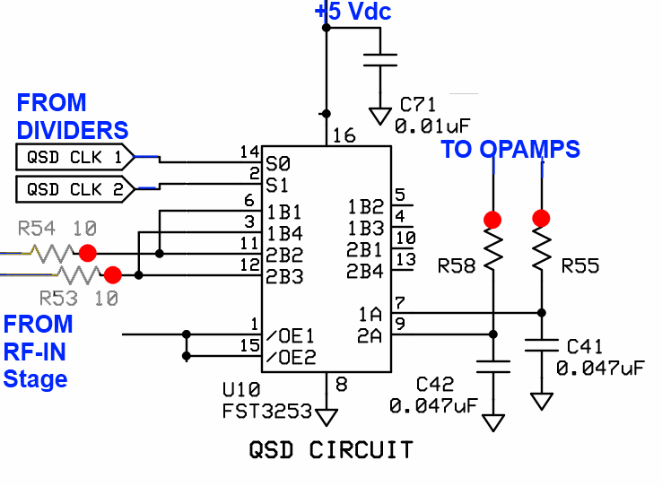
The mixer stage ("QSD" - Quadrature Sampling Detector) acts like two traditional direct conversion mixers operating in tandem. Each takes in half of the filtered RF from the bandpass filter stage and one of the quadrature center frequency signals, then "mixes"/down-converts them to with an output being the traditional mixer products, in this case, two (infra) audio frequency signals that represent the difference between the two inputs (RF and Local Oscillator). These two signals are referred to as the detected I (in-phase) and Q (Quadrature) signals and are fed into the high gain Op-Amps stage for amplification and delivery to the audio outputs (and, thence, to the PC's sound card). The mixer is enabled by the QSD enable line, switched in the RF I/O Control Stage's Q9. When the PTT line is activated, the QSD Enabling line goes high and disables the RX Mixer.
Summary Build Notes
Stage Schematic
Go to Top of Page
Click here for full schematic
(Red dots represent the "hairpin" (or left-hand or topmost) lead of the component)
Board Layouts
Board Top
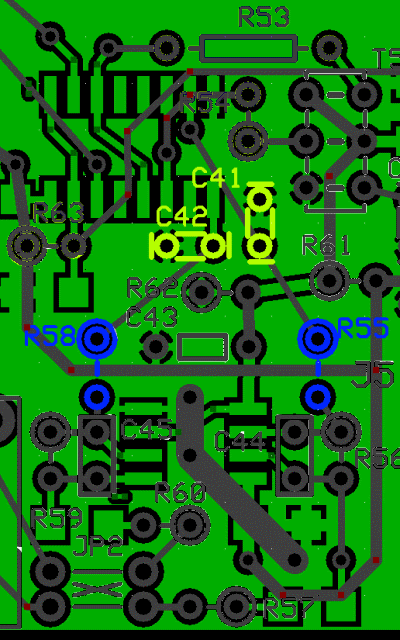
Go to Top of Page
Board Bottom
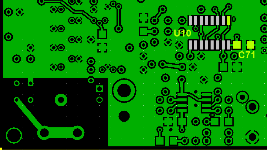
Go to Top of Page
RX Mixer (QSD) Bill of Materials
(30, 20, 17m band option)
(details for installation of each component are provided in the step instructions, further down the page)
Note: R53 and R54, which should have appeared in the completed board photos in the preceding stage, appear here. They had been inadvertently left out of the photos by the author
| Check | Type | Category | Component | Count | Marking | Image |
|---|---|---|---|---|---|---|
| ☐ | Capacitor | SMT 1206 | 0.01 uF | 1 | (smt) no stripe |

|
| ☐ | Capacitor | Ceramic | 0.047 uF 5% | 2 | 473 |

|
| ☐ | IC | SOIC-16 | FST3253 mux/demux switch | 1 | FST3253 ESD!!! |

|
| ☐ | Resistor | 1/4W | 10 ohm 1/4W 1% | 2 | br-blk-blk-gld-br |

|
Go to Top of Page
Detailed Build Steps
Step_Install Topside Components
| Check | Designation | Component (top/bottom) | Orientation | Marking | Image | Band | Notes |
|---|---|---|---|---|---|---|---|
| ☐ | C41 | 0.047 uF 5% (top) | 473 |
 |
any | ||
| ☐ | C42 | 0.047 uF 5% (top) | 473 |
 |
any |
Go to Top of Page
Step_Install Band-specific Components
The band-specific resistors are either 49.9 or 10 ohms (both have a GOLD 4th band. Do not get them mixed up with 10k or 4.99k resistors.
| Check | Designation | Component (top/bottom) | Orientation | Marking | Image | Band | Notes |
|---|---|---|---|---|---|---|---|
| ☐ | R55 | 10 ohm 1/4W 1% (top) | N-S | br-blk-blk-gld-br |
 |
30, 20, 17m | |
| ☐ | R58 | 10 ohm 1/4W 1% (top) | N-S | br-blk-blk-gld-br |
 |
30, 20, 17m |
Go to Top of Page
Step_Install Bottomside Components
| Check | Designation | Component (top/bottom) | Orientation | Marking | Image | Band | Notes |
|---|---|---|---|---|---|---|---|
| ☐ | C71 | 0.01 uF ((bottom)) | (smt) no stripe |
 |
any | ||
| ☐ | U10 | FST3253 mux/demux switch ((bottom)) | FST3253 ESD!!! |
 |
any |
Take extreme care working with this component. Always use ESD precautions.
|
Go to Top of Page
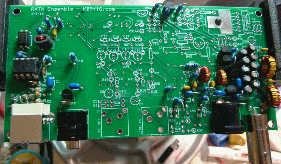
Completed Photos
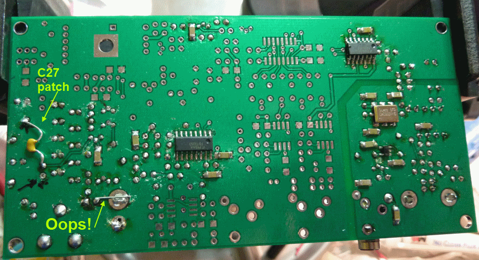
Author, while testing in this stage, accidentally shorted the 12V supply. The result was that the trace from the power socket to the diode was vaporized and had to be replaced with an underside patch. Also, this managed to "fry" the 74AC74 Quad Clock Generator IC:
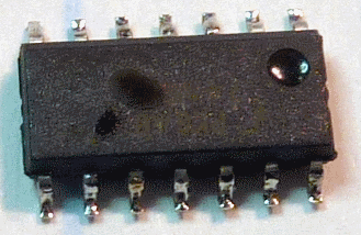
View of Completed Topside
View of Completed Underside
Go to Top of Page
Progressive Schematic
Where are we in our progress towards the finish line? Click here to view the entire schematic with the completed stages shaded in a yellowish tinge and the remaining stages tinted in blue (the current stage is untinted).
Test the RX Mixer (QSD) Stage
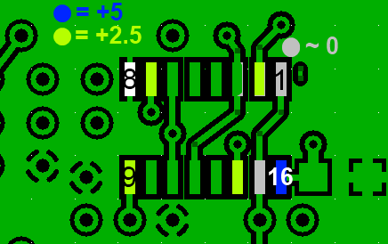
RX Mixer (QSD) - IC Pin Voltages
Test Setup
Note: The additional current draw of U10 is so low, the current draw test from the preceding stage should suffice
Voltages are measured WRT (regular) ground (R50 hairpin)
Power the board, connect USB to PC, run Rocky (to send PTT signal)
Measure pin voltages with PTT OFF
Measure Pin 1 and 15 voltages with PTT ON
It is best to test for these voltages at the actual pins (not the pads), thereby ensuring correct soldering of the pins to the pads.
Go to Top of Page
Test Steps (if any)
| Step | Test Point | UOM | Nominal | Author's | Builder's |
|---|---|---|---|---|---|
| 0 | Pin 8 | Vdc | 0 | 0 | |
| 1 | Pins 1 and 15 (PTT OFF) | mVdc | 0 - 50 | 50 | |
| 2 | Pin 2 (from Divider) | Vdc | 2.5 | 2.47 | |
| 3 | Pin 14 (from Divider) | Vdc | 2.5 | 2.47 | |
| 4 | Pin 7 (to OpAmp) | Vdc | 2.5 | 2.48 | |
| 5 | Pin 9 (to OpAmp) | Vdc | 2.5 | 2.48 | |
| 6 | Pin 16 (Vdd) | Vdc | 5 | 4.95 | |
| 7 | Pins 1 and 15 (PTT ON) | Vdc | high (Vdc) | 4.95 |
Go to Top of Page
RX Mixer (QSD) - Optional Mixer Test
Test Requirement (Optional)
At the antenna input, inject a signal that is 10 kHz above or below the selected center frequency.
Probe the hairpin leads of R55 and R58 for a 10 kHz audio frequency signal (in quadrature). You may use the hairpin of R50 for a ground point.
Go to Top of Page
Test Steps (if any)
Go to Top of Page