Ensemble RX II (HF/LF) Operational Amplifiers
Band: HF
Introduction
General Info About the Stage
Theory of Operation
Warren Allgyer, 9V1TD, has written an excellent posting on the Softrock40 reflector titled "Benchmarking the RX". There is some excellent theoretical and practical information, including suggestions for determining whether your RX is putting out adequate signal strength.
Stage Schematic
Go to Top of Page
Click here for full schematic
(Red dots represent the "hairpin" (or left-hand or topmost) lead of the component)

Summary Build Notes
Operational Amplifiers Bill of Materials
(HF band option)
(details for installation of each component are provided in the step instructions, further down the page)
| Check | Type | Category | Component | Count | Marking | Image |
|---|---|---|---|---|---|---|
| ☐ | Capacitor | Ceramic | 390 pF 5% | 2 | 391 |

|
| ☐ | Capacitor | SMT 1206 | 0.1 uF | 4 | (smt) black stripe |

|
| ☐ | Capacitor | Ceramic | 4.7 uF 10% 16V X7R RAD | 1 | 475 |
|
| ☐ | Connector | Jack-RA | 3.5mm stereo jack - PCB mount (rt-angle) | 1 |

|
|
| ☐ | IC | SOIC-8 | LT6231 dual op-amp | 1 | LT6231 ESD!!! |

|
| ☐ | Resistor | 1/6W | 120 1/6W 5% | 2 | brn-red-brn-gld |

|
| ☐ | Resistor | 1/4W | 4.99 k 1/4W 1% | 2 | y-w-w-br-br |

|
Go to Top of Page
Detailed Build Steps
Install Bottomside Parts
| Check | Designation | Component (top/bottom) | Orientation | Marking | Image | Band | Notes |
|---|---|---|---|---|---|---|---|
| ☐ | C46 | 0.1 uF ((bottom)) | yellow pads | (smt) black stripe |
|
any | |
| ☐ | C44 | 0.1 uF ((bottom)) | yellow pads | (smt) black stripe |
|
any | |
| ☐ | C45 | 0.1 uF ((bottom)) | yellow pads | (smt) black stripe |
|
any | |
| ☐ | C47 | 0.1 uF ((bottom)) | yellow pads | (smt) black stripe |
|
any | |
| ☐ | U11 | LT6231 dual op-amp ((bottom)) | (or LT6221) | LT6231 ESD!!! |
|
any |
Install Topside Parts
Careful - there are 1/6W and 1/4W resistors in this step.
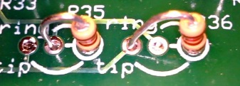
When installing the R35 and R36 to the line-in jack, the builder is advised to install them Such that R35 is spanning two holes as shown in the photo and R36 is spanning three holes. While the outputs would appear reversed to Rocky and Winrad, those two programs have a programmatic "switch I and Q lines" setting that can compensate. The PSDR versions do not have such a setting.

| Check | Designation | Component (top/bottom) | Orientation | Marking | Image | Band | Notes |
|---|---|---|---|---|---|---|---|
| ☐ | C21 | 4.7 uF 10% 16V X7R RAD (top) | horiz | 475 |
|
any | |
| ☐ | C22 | 390 pF 5% (top) | horiz | 391 |
|
any | |
| ☐ | C23 | 390 pF 5% (top) | vert | 391 |
|
any | |
| ☐ | R33 | 4.99 k 1/4W 1% (top) | N-S | y-w-w-br-br |
|
any | |
| ☐ | R34 | 4.99 k 1/4W 1% (top) | N-S | y-w-w-br-br |
|
any | |
| ☐ | R35 | 120 1/6W 5% (top) | E-W | brn-red-brn-gld |
|
any |
Spans 2 holes for J2 tip connection |
| ☐ | R36 | 120 1/6W 5% (top) | E-W | brn-red-brn-gld |
|
any |
Spans 2 holes for J2 ring connection |
| ☐ | J02 | 3.5mm stereo jack - PCB mount (rt-angle) (top) |
|
any |


Test the Operational Amplifiers Stage
Operational Amplifiers - Pin Voltage Tests
Test pin voltages WRT regular ground, as per graphic
As usual, if you are having any problems with this stage, be sure to measure the pin voltages two ways: first, measure each pin at the pin itself (on the IC). Then take a second measurement at the pin pad (on the board). If those two measurements do NOT agree, you very likely have a soldering issue.
If you are measuring zero volts where expected value is 2.5V, check the voltage at the right (hot) lead of C21 again (this was checked in the Auto Bandpass Filter stage and should have been ~2.5 Vdc in that check). If it is now zero, check for shorts.
Your op-amp outputs, pins 1 and 7, may be influenced by having the QSD circuit enabled since pins 1 and 15 of U10 are grounded.
Go to Top of Page
Test Steps (if any)
| Step | Test Point | UOM | Nominal | Author's | Builder's |
|---|---|---|---|---|---|
| 1 | Pin 1 (50% of 5V rail) | V dc | 2.5 | 2.57 | |
| 2 | Pin 2 (50% of 5V rail) | V dc | 2.5 | 2.47 | |
| 3 | Pin 3 (50% of 5V rail) | V dc | 2.5 | 2.47 | |
| 4 | Pin 4 (gnd) | V dc | 0 | 0 | |
| 5 | Pin 5 (50% of 5V rail) | V dc | 2.5 | 2.47 | |
| 6 | Pin 6 (50% of 5V rail) | V dc | 2.5 | 2.47 | |
| 7 | Pin 7 (50% of 5V rail) | V dc | 2.5 | 2.13 | |
| 8 | Pin 8 (5V rail) | V dc | 5 | 5.07 |
Go to Top of Page
Operational Amplifiers - Functional Test
Test Setup
Test the First OpAmp
- Power up the circuit and measure the voltage at pin 1 of the op-amp (hairpin of R33). It should be ~2.5 Vdc
- Power off and use clip leads to connect Rb between the hairpin of R31 and circuit ground. This provides an input resistance(Ri) of 10 kΩ, to the op-amp.
- Power up and measure the output voltage (WRT regular ground) at the hairpin of the feedback resistor R33. You should get ~3.75 Vdc at R33 hairpin.
- Remove Rb and the output voltage at R33 should go back to ~2.5 Vdc.
Test the Second OpAmp
- Power up the circuit and measure the voltage at pin 1 of the op-amp (hairpin of R34). It should be ~2.5 Vdc
- Power off and use clip leads to connect Rb between the hairpin of R30 and circuit ground. This provides an input resistance(Ri) 10 kΩ, to the op-amp.
- Power up and measure the output voltage (WRT regular ground) at the hairpin of the feedback resistor R34. You should get: ~3.75 Vdc at R34 hairpin.
- Remove Rb and the output voltage at R34 should go back to ~2.5 Vdc.
The diagram above show the test points. The yellow dots show the Rb connection points for each "side" of the opamps. The dots marked "A" and "B" show the measurement points for the output voltages for Each "side" of the OpAmps.
An Excel spreadsheet with a calculator for this test is available for you to plug in your bridging resistor ohms (Rt) and your pin 1 or pin 7 normal voltages (Ebias) and predict the expected voltage when bridged (Eout).
If your results are not as nominally expected, double check the values of R33 and R34 (both 4.99k, NOT 49.9). See this message thread on the Yahoo Softrock40 reflector.
Go to Top of Page
Test Steps (if any)
| Step | Test Point | UOM | Nominal | Author's | Builder's |
|---|---|---|---|---|---|
| 1 | "A" (hairpin lead of R33 (NOT bridged) | V dc | 2.5 | 2.57 | |
| 2 | "A" (hairpin lead of R33 (bridged) | V dc | 3.75 | 3.80 | |
| 3 | "B" (hairpin lead of R34 (NOT bridged) | V dc | 2.5 | 2.13 | |
| 4 | "B" (hairpin lead of R34 (bridged) | V dc | 3.75 | 3.44 |
Go to Top of Page
Operational Amplifiers - RX Test
Prepare an SDR program for RX (author recommends Rocky for the Windows XP crowd; HDSDR or SDR# for other Windows OS). This usually involves downloading and installing the program; selecting the desired soundcard for the (STEREO) input of the I and Q signals from the board; and connecting the board to the soundcard with a stereo cable with 1/8" stereo plugs on either end.
Probably the easiest of all these software offerings to setup is SDR# ("SDR Sharp"). Alan, G4ZFQ, has a nice tutorial on his site that illustrates the setup and initial operation of SDR#. SDR# handles the Si570 driver situation pretty smoothly.
If your preference is HDSDR, check out the WB5RVZ How-To on setting up HDSDR for RX.
Once the SDR program is ready, connect the USB cable from your PC to the board, connect the 12V power to the board, and connect a 50 ohm antenna to J4.
Connect the "Line-In" jack on the pc board to the "Line-In" input jack on the pc or sound card, using a length of male-to-male stereo audio cable, with 18/" stereo plugs
Start the SDR program and adjust the LO frequency to the desired center frequency. You should see signals in the displayed spectrum. If there is a contest going on at test time, you will be even more impressed with the RX!
Note: for either SDR program to work with the Ensemble RX, you MUST have installed the driver (libusb) for the Microcontroller's USB functionality. For HDSDR, you will also need to have downloaded and saved in the same directory as HDSDR, the EXTIO_Si570.dll file.
If you are seeing perfect mirror inages of the signals either side of the center frequency, you should review the information in the Image Rejection Hints page.
If you installed the R35 and R36 as suggested, you will need (in Rocky and/or HDSDR) to switch the I and Q inputs to get signals properly arrayed on the correct "side" of the center frequency and to make USB and LSB modes work correctly.
Rocky has a setting in the "Audio" settings tab. Make sure it is set to "Left/Right=Q/I".
SDR# does not need to switch the I and Q inputs.
The setting for HDSDR is under "Options (F7)", where you can check to "Swap I and Q Channel for RX".
Ground Loops and Humps
If you experience a large "hump" at the center frequency or several spurii on the spectrum, you may be the victim of ground loops.
Alan G4ZFQ has an excellent article on the effects of ground loops on the SDR and how to minimize/avoid them. (OK, Alan, so it's "minimise"!)
Another great resource from Alan is his page on "SDR with SoundCard Basic Faults" (which graphically shows what poor grounding can do in a sound-card-based SDR application).
Go to Top of Page
Test Steps (if any)
Go to Top of Page