Softrock Lite II Softrock Lite II: Operational Amplifiers
Band: 20m
Introduction
General Info About the Stage
Theory of Operation
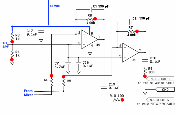
The low-level In-Phase (I) and Quadrature (Q) IF signals from the Mixer are sampled over capacitors C5 and C6 (in the Mixer stage).
The opamps in this stage amplify the I and Q baseband signals by a factor of approximately 499, to compensate for the attenuation as a result of subharmonic quadrature sampling .
Go to Top of Page
Stage Schematic
Go to Top of Page
Board Layouts
Board Top

Go to Top of Page
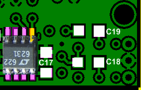
Board Bottom
Go to Top of Page
Operational Amplifiers Bill of Materials
( 20m band option)
(details for installation of each component are provided in the step instructions, further down the page)
| Check | Type | Category | Component | Count | Marking | Image |
|---|---|---|---|---|---|---|
| ☐ | Capacitor | Ceramic | 390 pF 5% | 2 | 391 |

|
| ☐ | Capacitor | Ceramic | 4.7 uF 10% 16V X7R RAD | 1 | 475 |

|
| ☐ | IC | SOIC-8 | LT6231 dual op-amp | 1 | LT6231 ESD!!! |

|
| ☐ | Resistor | 1/4W | 10 ohm 1/4W 1% | 2 | br-blk-blk-gld-br |

|
| ☐ | Resistor | 1/6W | 100 1/6W 5% | 2 | br-blk-br-gld |

|
| ☐ | Resistor | 1/4W | 1 k 1/4W 1% | 2 | br-blk-blk-br-br |

|
| ☐ | Resistor | 1/4W | 4.99 k 1/4W 1% | 2 | y-w-w-br-br |

|
Go to Top of Page
Detailed Build Steps
Install OpAmp
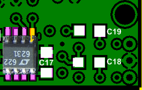
Install the LT6231 operational amplifier to the bottomside of the board.
See hints on installing SMT ICs.
- Orient U4 on its pads so that the pin 1 corner of the IC matches the small “1" (it also looks like a “0”) mark in the copper on the bottom side of the board. In general, pin 1 of an SOIC packaged IC is in the lower left corner of the package when the printing on the package top reads upright, from left to right.
- Tack-solder one corner pin of U4 and reheat the tacked pin as necessary to line up U4 on its pads properly.
- Double-check the orientation of U4 and the line up of the IC on its pads with magnification and good lighting. You do NOT want to install U4 oriented incorrectly. If all is well, carefully solder the rest of the leads to their pads.
| Check | Designation | Component (top/bottom) | Orientation | Marking | Image | Band | Notes |
|---|---|---|---|---|---|---|---|
| ☐ | U4 | LT6231 dual op-amp ((bottom)) |  |
LT6231 ESD!!! |
 |
any |
Install band-specific components
Install the band-specific capacitors and resistors.
See hints on orienting and installing resistors.
See hints on identifying and installing ceramic caps.
| Check | Designation | Component (top/bottom) | Orientation | Marking | Image | Band | Notes |
|---|---|---|---|---|---|---|---|
| ☐ | R05 | 10 ohm 1/4W 1% (top) | E-W | br-blk-blk-gld-br |
 |
20m | |
| ☐ | R06 | 10 ohm 1/4W 1% (top) | E-W | br-blk-blk-gld-br |
 |
20m |
Install remaining components
See hints on orienting and installing resistors.
See hints on identifying and installing ceramic caps.
| Check | Designation | Component (top/bottom) | Orientation | Marking | Image | Band | Notes |
|---|---|---|---|---|---|---|---|
| ☐ | C08 | 390 pF 5% (top) | 391 |
 |
any | ||
| ☐ | C09 | 390 pF 5% (top) | 391 |
 |
any | ||
| ☐ | C07 | 4.7 uF 10% 16V X7R RAD (top) | 475 |
 |
any | ||
| ☐ | R07 | 4.99 k 1/4W 1% (top) | S-N | y-w-w-br-br |
 |
any | |
| ☐ | R03 | 1 k 1/4W 1% (top) | W-E | br-blk-blk-br-br |
 |
any | |
| ☐ | R08 | 4.99 k 1/4W 1% (top) | E-W | y-w-w-br-br |
 |
any | |
| ☐ | R04 | 1 k 1/4W 1% (top) | W-E | br-blk-blk-br-br |
 |
any | |
| ☐ | R09 | 100 1/6W 5% (top) | E-W | br-blk-br-gld |
 |
any | |
| ☐ | R10 | 100 1/6W 5% (top) | E-W | br-blk-br-gld |
 |
any |
Go to Top of Page
Completed Photos
Note: the completed pictures are of the 40m option, which the author built. Other band options (which the author did not build) will appear slightly different (especially the inductors, whose windings and cores will vary by band) for the band-specific components.
View of Completed Topside
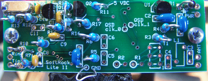
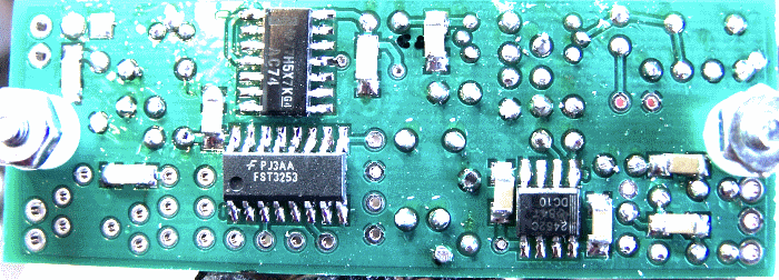
View of Completed Underside
Go to Top of Page
Testing
Overview
Warning
Take appropriate ESD precautions in these tests, since you will be working around the sensitive OpAmp ICVisual Check
Test Setup
Using very good lighting and magnification, carefully inspect the solder joints to identify bridges, cold joints, or poor contacts.
Pay especial attention to the joints on the OpAmp IC pins. If necessary, touch up the joints with your iron and/or some flux. Wick up any excess.
Current Draw
Test Setup
- In each test, the ammeter must be placed in series between the positive lead of the power source and the board's positive power-in "+" terminal.
- In one test there is also a 100 ohm resistor in the series "chain" as well.
- in the second test, the setup is the same except that the current-liminting resistor is removed
Apply 12 Vdc to the board for this test
Test Measurements
| Testpoint | Units | Nominal Value | Author's | Yours |
|---|---|---|---|---|
| With 100 ohm current-limiting resistor | mA | < 30 | 26.6 | _______ |
| Without current limiting resistor | mA | < 30 | 26.9 | _______ |
Voltage Tests
Test Setup
Measure the voltages with respect to ground for each of the pins of U4. Tage care to measure at the actual IC pin rather than the pad, so as to ensure you are measuring the PIN voltage
expected voltages are indicated in the table below:
- 5 V (range of 4.5 - 5.4)
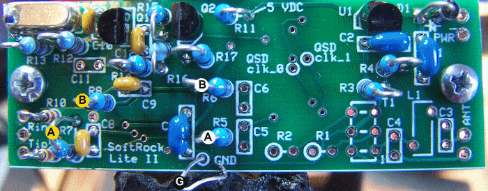
- 2.5 V (approx 50% of the 5V rail value)

 Functional Test"