Softrock_40_R External Connections
Band: 20m
Introduction
This stage involves connecting the stereo cable to the outputs of the opamps and connecting the short coax wires to the ANT/RET terminals. The software activities will be developed soon. In the meantime, refer to the similar procedures on the SR Lite II documentation for external connections and Rocky Software Installation
General Info About the Stage
Theory of Operation
This receiver makes certain assumptions about the external environment to which it is connected:
- 50 ohm Antenna: The antenna connected to this RX must be close to 50 ohms impedance for the bandpass filters to act effectively. A serious mismatch can cause very poor reception.
- Stereo Sound Card Inputs: For the PC to be able to operate independently on the I and Q outputs of this receiver, the sound card to which these must be input MUST have a STEREO input. The most common complaint about these I/Q RX kits is from the builder who runs the inputs into the "MIC" input of his laptop, assuming the "MIC" input is stereo when, in fact, it is mono. The common symptom of this is the appearance of two exaclt identical signals on either side of the "center-frequency" in the spectrum display of the SDR software.
Stage Schematic

Go to Top of Page
Board Layouts
Board Top

Go to Top of Page
Board Bottom

Go to Top of Page
External Connections Bill of Materials
( 20m band option)
(details for installation of each component are provided in the step instructions, further down the page)
| Check | Type | Category | Component | Count | Marking | Image |
|---|---|---|---|---|---|---|
| ☐ | Cable | Cable, antenna | antenna COAX | 1 |

|
|
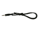
| ☐ | Cable | Cable, Audio | Stereo Audio Shld Cable, single 1/8" plug | 1 |

|
|
| ☐ | wire | Hookup | misc hookup wire | 1 |
Go to Top of Page
Detailed Build Steps
Install Cables
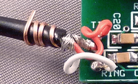
The audio cable provided (at least the author;s version) is two conductor with ground wire wrapped around the 2 conductors. The "TIP" conductor is a red wire; the "RING" conductor is a white wire.
Prepare the audio cable, stripping and tinning the red and white wires and soldering the common (shield) sheaf to a short length of hookup wire. This hookup wire, provided in the cable bag, will be wrapped arounf the cable at the point of connection to the board and then soldered into the "common" hole (between the "TIP" and "RING" holes, so as to have the hookup wire take the strain/stress from the cable.
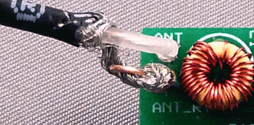
Similarly, connect the coax cable's center conductor to the "ANT" hole and the braid to the "ANT-RET" hole. (The author used a bit of hookup wire soldered to the braid to make the actual connection to the ANT-RET hole).


| Check | Designation | Component | top/Bottom | Marking | Image | Band | |
|---|---|---|---|---|---|---|---|
| ☐ | strain_relief | misc hookup wire (top) | any | ||||
| ☐ | cbl-audio | Stereo Audio Shld Cable, single 1/8" plug (top) |
 |
any | |||
| ☐ | cbl_ant | antenna COAX (top) |
 |
any | Yada not furnished with kit |
Install Software
TBD: This step will describe the installation and use of the new SDR program "SDR Sharp" (or "SDR#").
See also the writeup by Alan G4ZFQ on installing SDR# (and Rocky)
In the meantime, the process of installing and using Rocky v3.7 (as described in the SR-LITE II kit builders notes may be used
| Check | Designation | Component | top/Bottom | Marking | Image | Band |
|---|
Connect Radio
Once the cables are installed and the Software installed and tested, the only thing remaining is to connect the radio to the PC and to the Antenna.
- Connect the antenna cable to a 50 ohm antenna
- plug the audio plug at the end of the audio calble into the "Line-In" jack of your PC's sound card. (Note: MUST BE STEREO")
- Plug the Softrock 40-R's USB plug into a convenient USB jack on your PC
- Start up the SDR software: Configure the software so it recognizes the center frequency for the Softrock 40-R (e.g., 20m is 14.047MHz)
- Enjoy!
| Check | Designation | Component | top/Bottom | Marking | Image | Band |
|---|
Completed Photos
View of Completed Topside

View of Completed Underside

Go to Top of Page
Testing
Overview
Name of Test
Test Procedure
Potential issues:
Test Table
| Seq | Test Point | Units | Nominal Value |
Author's Value | Your Value |
|---|---|---|---|---|---|
| 1 ☐ | "A" on | unit | nom | authtbd | ___________ |
| 2 ☐ | "B" on | unit | nom | authtbd | ___________ |