Softrock_40_R Home - Softrock 40 R2 USB RX
Band: 20m
Introduction
General Info
Bands
This kit comes in multiple band options: 160m, 80m, 40m, 30m, or 20m (the one I built). If you are building for one of the other bands, click on the "Bands" tab in the above navigation menu to select your band. The system will remember the band so long as you stay connected to the site. Still, it is a good idea to verify the band in the heading of each page, so that, if for some reason the "sticky" band value has somehow reverted back to the default of 20m, you can reselect your desired band.
Good Buid Blog on Facebook
To whet your appetite, check out Dave Watson's Softrock40 build blog on Facebook.
SMT
The most difficult part of this build is making sure you do not lose any of the SMT components. The resistors and capacitors are very small and extremely lightweight. They can be accidentally "launched" by a shaky hand and a bad set of tweezers. Invest in a good set of tweezers and a baking sheet with 0.5-1" walls around the edges. If a chip ever lands in the carpet, you will never find it!
Pix and Tests
This kit's pictures and test results were based upon my build of the kit for the 20m band. Results may vary somewhat for other bands. Frequency-oriented tests show nominal values based upon the crystal frequency for the selected band.
Theory of Operaton
- This receiver is patterned on the classic "direct conversion" receiver, in that it mixes incoming RF down to audio frequencies by, in effect, beating the RF against a Local oscillator such that the mixer products are in the sub 100 kHz range.
- Unlike the traditional DC receiver, the SDR does not "tune" the local oscillator's frequency to beat up against a desired RF signal. Instead, the local oscillator is at a fixed frequency.
- As a result, the (baseband) mixer products can vary in frequency from zero to +/- some theoretically high super-audio frequency. In fact, the practical limit is one-half the soundcard's maximum sampling rate.
- The "tuning" (and demodulation and AFC and other neat radio things) happen in the software part of the Software Defined Radio. It is the magic of Software that makes for the extraordinarily high selectivity in the direct conversion hardware (which is notorious for great sensitivity but terrible selectivity).
- The software requires the mixer's baseband products to be provided to the PC as two separate signals, each identical to the other, except that they are 90 degrees apart in phase ("in quadrature"). The SR Lite II achieves this by dividing the local oscillator's frequency by 4 (with attendant phase shifts to achieve quadrature).
- The output of the divider chain is two signals, I (In-Phase) and Q (Quadrature), identical in all respects but phase i.e., they are "in quadrature"). These signals are harmonically rich, a fact of which the 20m band option takes advantage. This permits us to generate signals whose fundamental frequencies are 4.6825, with a third harmonic of 14.0475 MHz.
- RF from the antenna is bandpass-filtered for the 20m band.
- The two quadrature signals from the Divider stage are fed into the mixer stage, which mixes the third harmonic of the LO, 14.0475 MHz, with the bandpass-filtered 20m RF down to two baseband signals that are also in quadrature and otherwise identical to each other.
- These two signals are provided to an amplifier stage where they are amplified and low-pass filtered to levels acceptable to the PC's soundcard stereo line-in inputs.
- A soundcard which can sample 48 kHz, can digitize an incoming "chunk" of baseband signals from 0 to 24 kHz. Such a soundcard, using its stereo line-in inputs for the I and Q signals, will yield an effective bandwidth of 48 kHz: 24 kHz above the center frequency and 24 kHz below the center frequency. The SDR software in the PC manipulates the digitized I and Q signals to deliver, demodulate, condition, and filter signals within this 48 kHz spectrum.
- Soundcards capable of higher sampling rates (e.g. 96 kHz or 192 kHz) will yield proportionately wider bandwidth, provided their internal audio filters do not cut off the higher audio frequencies.
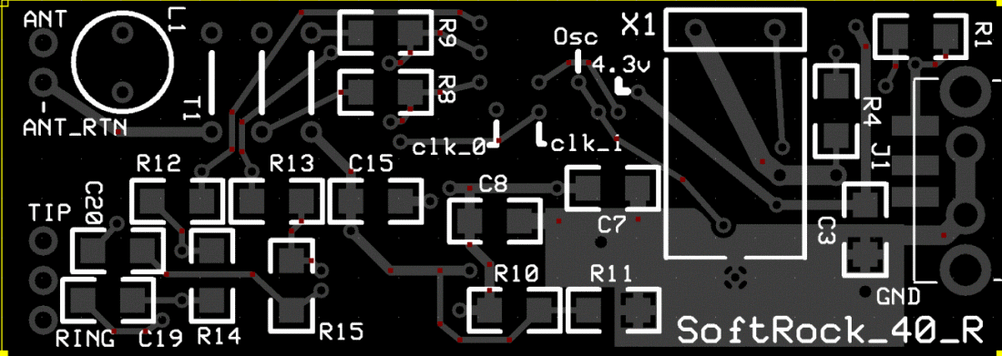
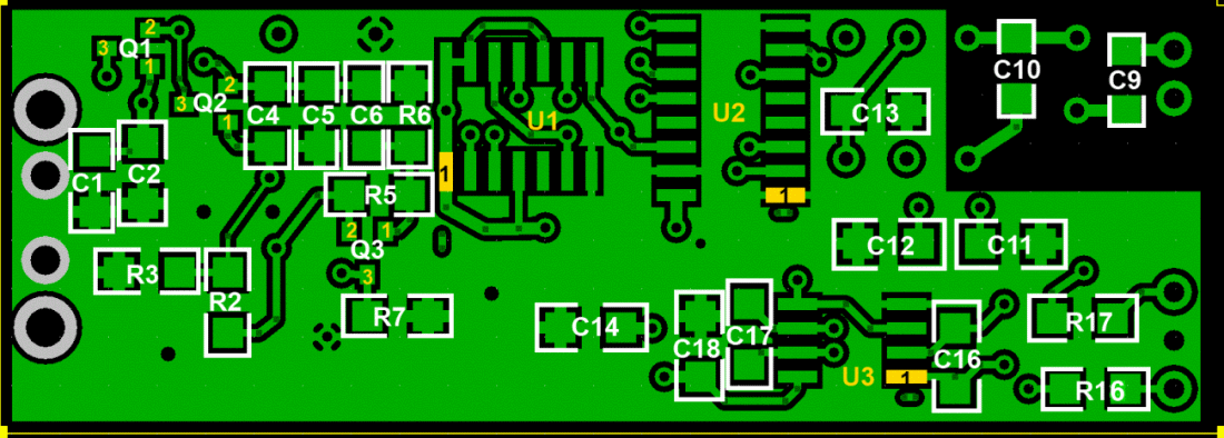
Board Layouts
Topside

Underside

Completed Images
Note: the completed pictures are of the 20m option, which the author built. Other band options (which the author did not build) will appear slightly different (especially the inductors, whose windings and cores will vary by band) for the band-specific components.
Topside

Underside

